Define the assay layout
Define how the samples are arranged on the plate for this use case.
Before you begin
About this task
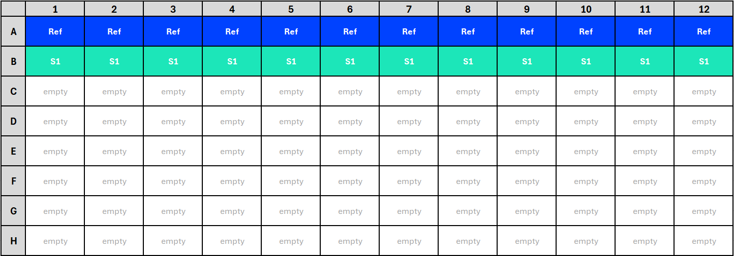
For this use case, you work with an assay with a 96-well plate layout. On the plate, you use wells A1 to A12 for the standard (reference) and wells B1 to B12 for the test sample. The rest of the wells remain empty.
Defining plate layouts involves
two steps. First, you assign assay elements to wells. Next, you
assign dilutions or sequence steps to wells. To perform these
assignments, you use the primary display factor drop-down list
(![]() ) in the
toolbar of the By Position
editor. For details on this editor, see the By Position editor topic.
) in the
toolbar of the By Position
editor. For details on this editor, see the By Position editor topic.
Procedure
- In the By Position editor, select Observation group ID as the primary display factor.
-
Assign samples to wells according to the following logic:
Cells Observation Group ID A1 to A12
[1] Standard sample: Ref
B1 to B12
[2] Test sample: S1
C1 to H12
Do not make any assignments.
Results: Your plate layout should now look like this:
Figure 2. Assignment of assay elements to wells in the By Position editor, using the Observation group ID primary display factor (cropped) -
Select Sequence step as the primary display factor and
assign dilutions to sequence steps according to the following logic:
Cells Sequence step A1 and B1
[1] 5
A2 and B2
[2] 3.33
A3 and B3
[3] 2.22
A4 and B4
[4] 1.48
A5 and B5
[5] 0.99
A6 and B6
[6] 0.66
A7 and B7
[7] 0.44
A8 and B8
[8] 0.29
A9 and B9
[9] 0.2
A10 and B10
[10] 0.13
A11 and B11
[11] 0.09
A12 and B12
[12] 0.06
C1 to H12
Do not make any assignments.
Results: Your plate layout should now look like this: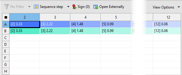
Figure 3. Assignment of dilutions to sequence steps in the By Position editor, using the Sequence step primary display factor (cropped) - Save the template.